Lab Two: Common Emitter Amplifier
Building and Measuring the DC Circuit
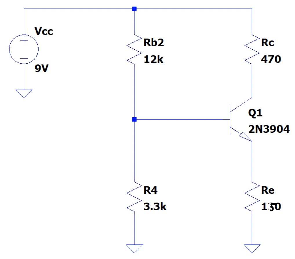
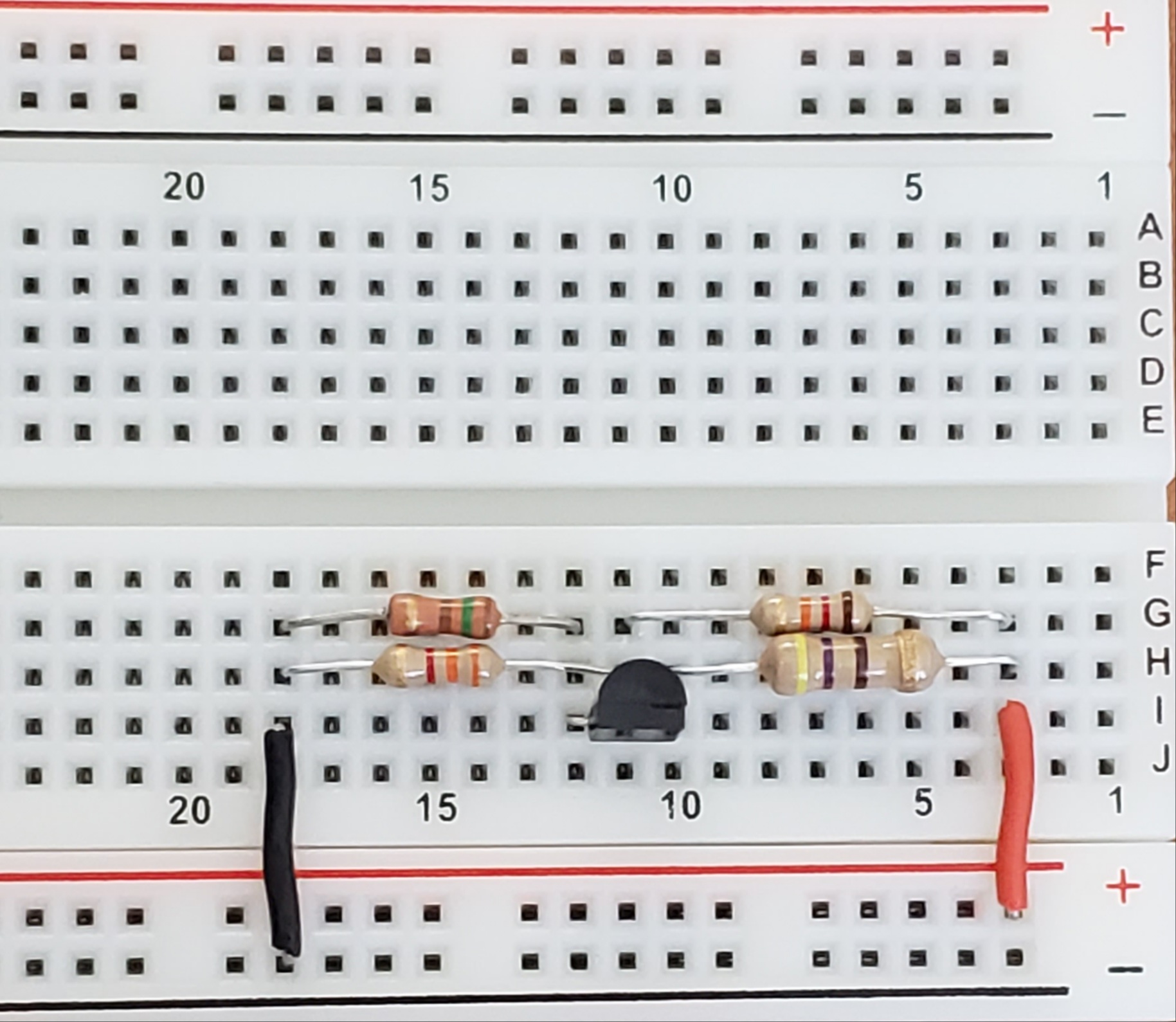
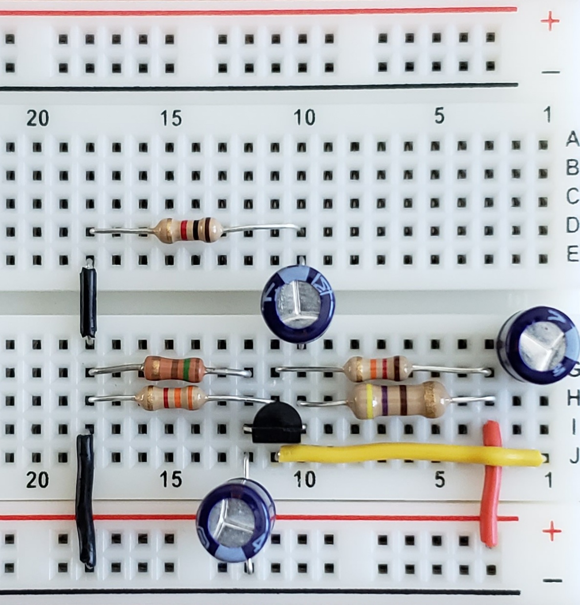
The circuit shown in Figure 1 is a four-resistor biased NPN transistor. This network serves as a basic amplifier of a given input signal once several AC components are added. This circuit is then created on a breadboard as shown in Figure 2. Next, \(V_{BE}\) is measured to be \(0.69V\) and \(V_{CE}\) is measured as \(4.36V\). Now the q-point is measured using a digital multimeter. The q-point is defined as \((V_{CE}, I_C)\) and measured to be \((4.2V, 0.3mA)\).
Adding the AC Portion
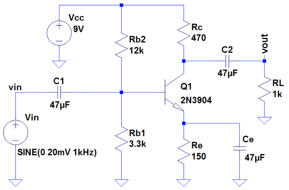
Now the AC portion as showin in Figure 3 is added to the breadboard as shown in Figure 4. The circuit now functions as an analog amplifier given an input on the breadboard rail number two.
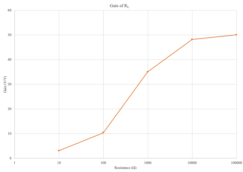
The gain of the amplifier is now measured as \(R_L\) is varied from \(10\Omega\) to \(100k\Omega\) as shown in Table 1 and Graph 1.
\begin{array} {|c|c|} \hline R_1(\Omega) & Gain \frac{V}{V}\\ \hline 10 & 3.07 \\ 100 & 10.35 \\ 1k & 35 \\ 10k & 48.125 \\ 100k & 50 \\ \hline \end{array}
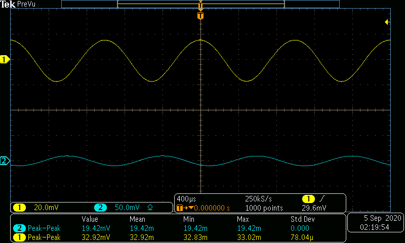
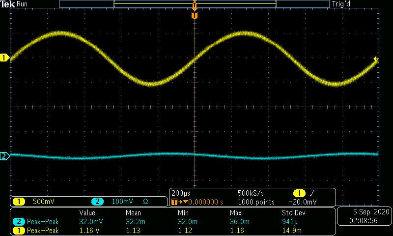
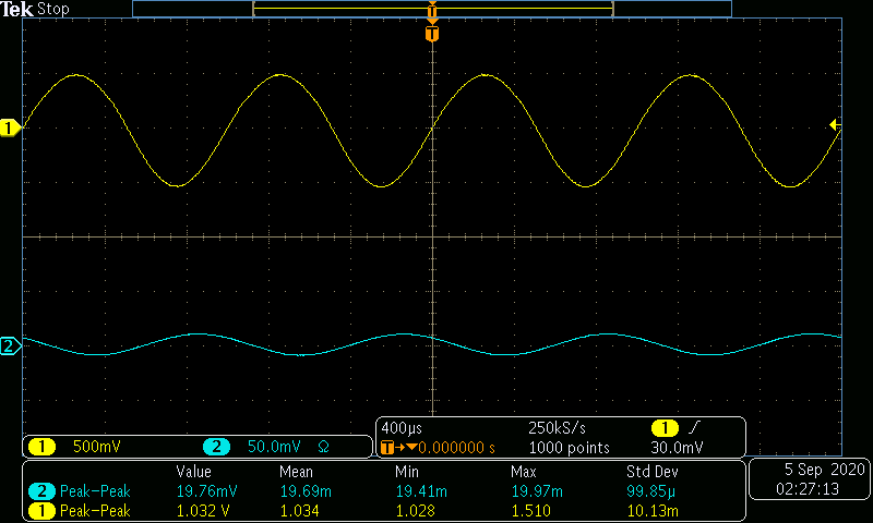
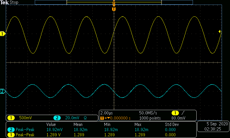
The gain shown above is taken from data collected using an oscilloscope. Due to the varying nature of measurements, the data shown in the below screenshots (Figures 5-7) do not line up directly with the above graph. From left to right, the Figures are taken from \(R_L = 10\Omega\), \(R_L = 1k\Omega\), and \(R_L = 100k\Omega\).
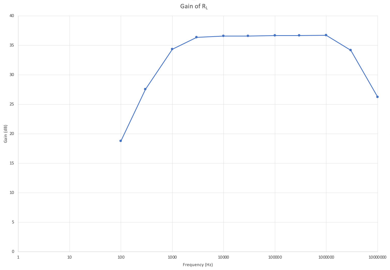
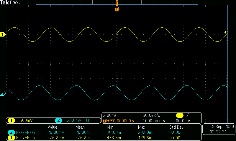
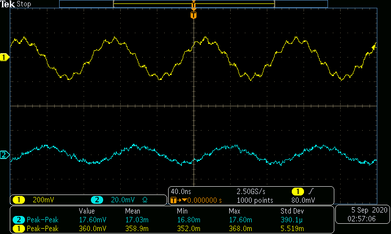
The AC input frequency is now varried from a range of 100Hz to 10MHz. A sample of a low, medium, and high input frequency is shown in Figures 8-10. Table 2 and Graph 2 show the gain in dB as the frequency is varied.
\begin{array} {|c|c|c|} \hline Frequency (Hz) & Voltage Gain \frac{V}{V} & Gain(dB)\\ \hline 100 & 8.67 & 18.77 \\ 300 & 23.84 & 27.54 \\ 1k & 52.22 & 34.35 \\ 3k & 65.79 & 36.36 \\ 10k & 67.53 & 36.59 \\ 30k & 67.54 & 36.59 \\ 100k & 68.01 & 36.65 \\ 300k & 68.12 & 36.67 \\ 1M & 68.65 & 36.73 \\ 3M & 51.10 & 34.17 \\ 10M & 20.45 & 26.22 \\ \hline \end{array}